Print Server Power Control Hack
Power Control Box
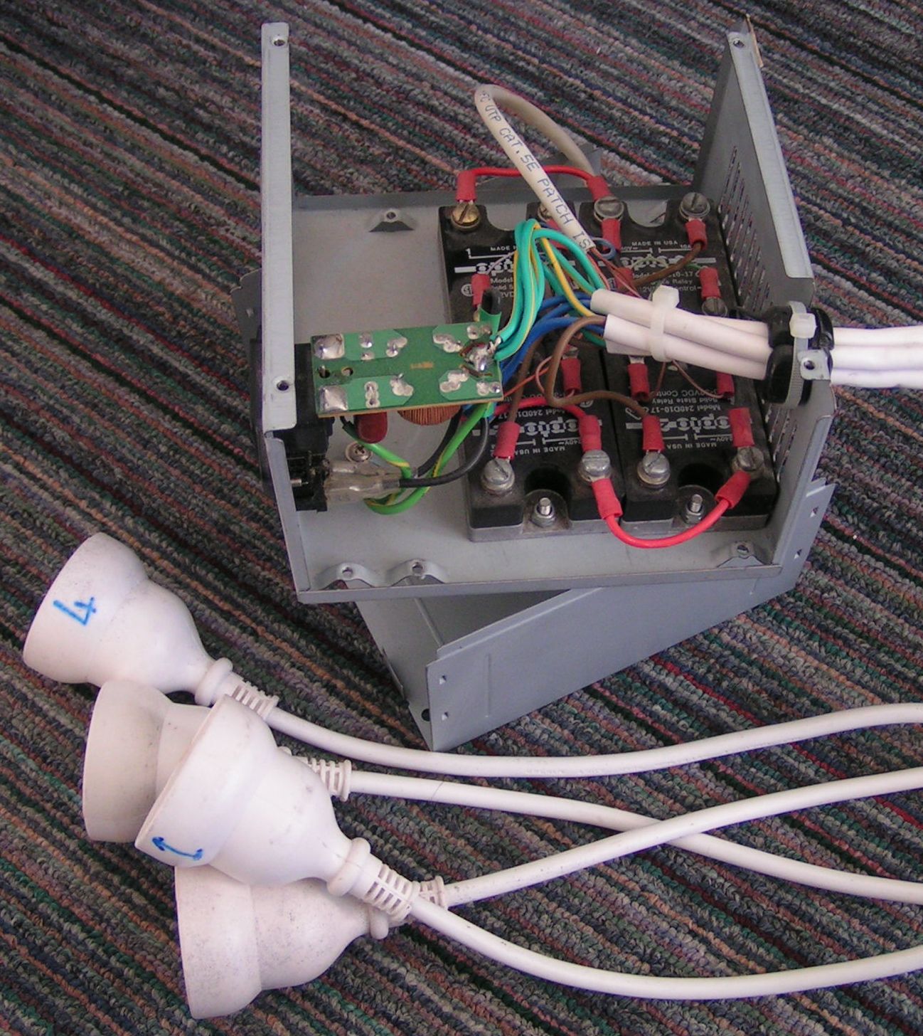
A few years a go I built this solid-state relay power control box.
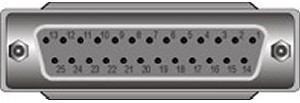
It connects to a parallel port allowing me to turn the power points on and off using software. The parallel port allows for up to 8 outputs by using data 0 through 7 (Pins 2 though 9).
I’ve had this box attached to my HTPC for the last few years; I use it to control power to my TV, subwoofer, table lamp etc.
As mentioned in my previous posts I’ve just finished building a new HTPC, and guess what, it has no parallel port! I thought it would be a simple case of using a USB to parallel adaptor but unfortunately these adaptors aren’t seen by windows as standard parallel ports; instead it appears in device manager as a “USB Printing Support” device hence can’t be addressed directly to turn the data pins on and off.
Print Server
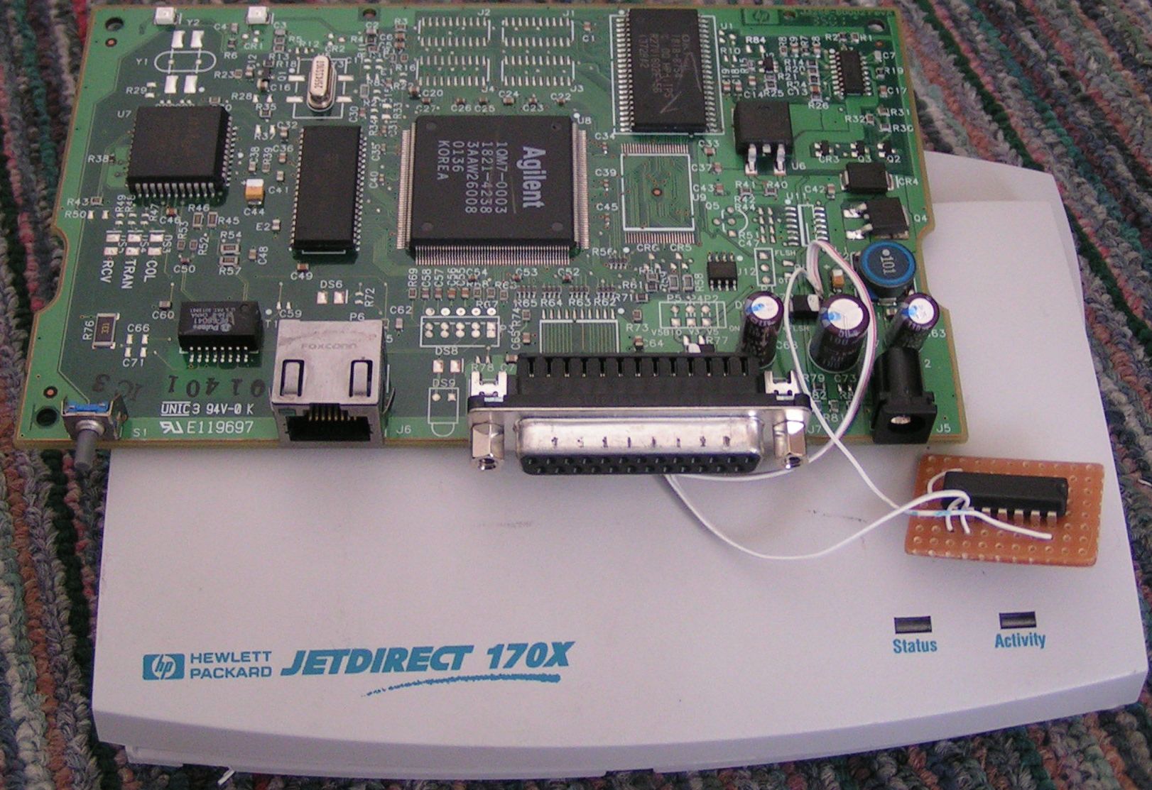
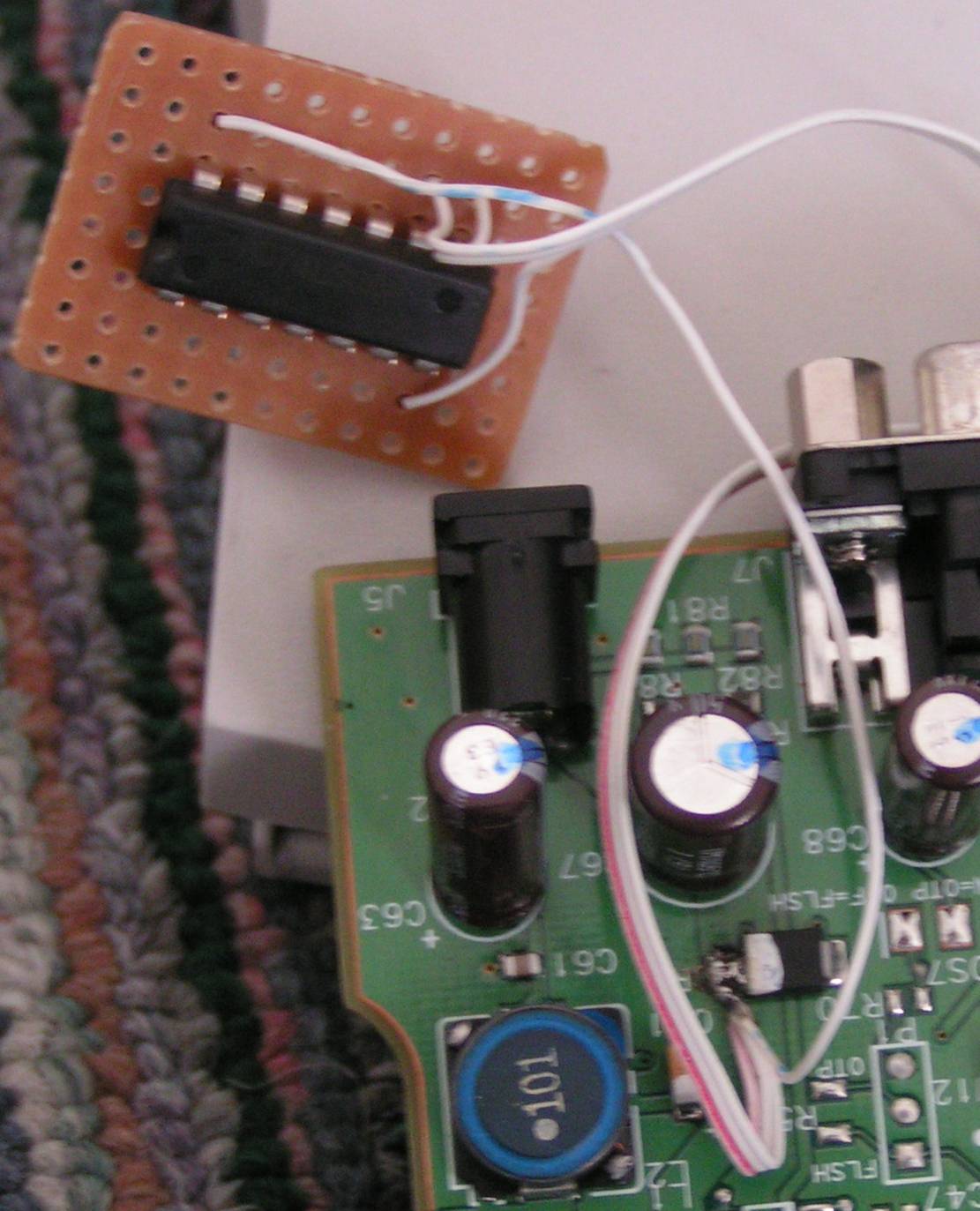
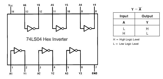
After much googling I came across a project by Doktor Andy which uses a network print server to drive external devices. This was perfect since I had a HP JetDirect print server. I wasn’t able to get Doktor Andy’s circuit working with the JetDirect but Boyan Biandov who’s name was on Andy’s site was very helpful and told me how to get the JetDirect working. A single 74LS04 chip is all that is required to invert the strobe output and feed it back into the busy input, I’m not really a wiz with electronics but as I understand it this fools the print server in to thinking that there is a printer attached and everything is “ok”.
* EDIT *
You DON’T need to use the additional chip at all. Fred kindly commented and pointed this out:
I have a trick to remove the 74ls04 chip : told the printserver ignore the busy data
a simple setting with any snmp tool
1.3.6.1.4.1.11.2.4.3.13.4.0
npPortCentronicsHandshaking OBJECT-TYPE
SYNTAX INTEGER {
nack-and-busy(1),
nack-only(2),
busy-only(3)
}
ACCESS read-write
STATUS optional
DESCRIPTION
“The handshaking to be used in sending data over the parallel port.”
::={ npPort 4 }
Smply change the value to 2
Gerrit and Milan have included some step-by-step instructions and a video below in the comments below on how to set this SNMP option.
Thanks to all have contacted me and contributed!
* EDIT *
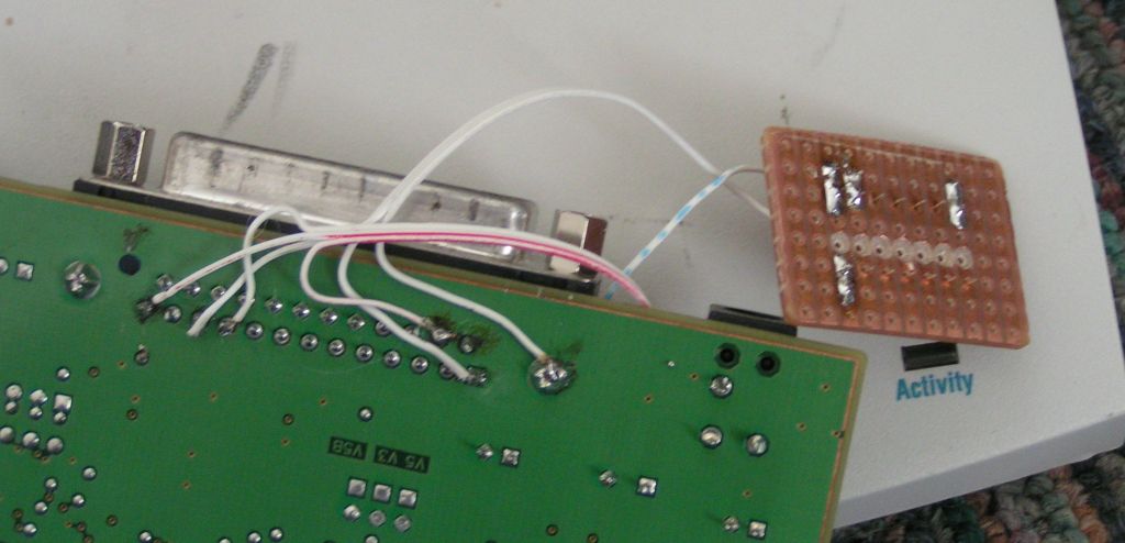
The IC requires +5Volts and it is also nessecicary to connect +5volts to pins 10, 13 and 15. It wasn’t hard to find a +5v point on the print server board.
Connections; What needs to be connected to what:

Credit goes to Doktor Andy for this great idea and BIG thanks to Boyan who gave me just the right info when I was about to give up!
Control Software
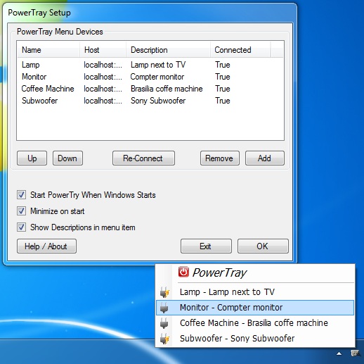
I’ve created a full windows application to control devices attached to print servers, local parallel ports and K8055 USB boards. Download and read about it here.
Here is the simple c#.net class which I use to access the print server. Say you wanted to turn on pins 2, 4 and 6. Combine the pin values
Pin2=1
Pin3=2
Pin4=4
Pin5=8
Pin6=16
Pin7=32
Pin8=64
Pin9=128
Required value to tun on pins 2, 4 and 6 is 1+4+16=21
Call the output method specifying the port as ipaddress:port and the output value:
(Most print servers use tcp port 9100, multi port JetDirects use 9100 for port one, 9101 for port two etc)
IpPortAccess.Output(192.168.1.10:9100,21);
using System.Net;
using System.Net.Sockets;
using System;
using System.Collections.Generic;
using System.Text;
namespace PowerControl
{ class IpPortAccess
    { public static void Output(string port,int value)
        {
            string[] ipport = port.Split(new char[] { ':' });
            string _ip = ipport[0]; int _port = Convert.ToInt32(ipport[1]);
            Socket soc = new Socket(AddressFamily.InterNetwork, SocketType.Stream, ProtocolType.Tcp); soc.Connect(_ip,_port);
            byte[] sendData = new byte[1];
            sendData[0] = Convert.ToByte(value);
            soc.Send(sendData);
            soc.Close();
            }
       }
}
