Brasilia Espresso Machine Restoration and PID Upgrade
I’ve been working on this project on and off for a few years. It started off as a simple restoration of a second hand Italian espresso machine which quickly got out of control, as most of my projects seem to do. Here’s a video showing the finished project and then a bunch of photos showing the build. I should have done the video with the camera turned the other way, sorry about that but I couldn’t be bothered re-doing it.
The Brasilia ‘Lady’ is a very simple single-group, single boiler machine. It has a 300ml brass boiler with a 3-way solenoid valve. It has a simple bimetallic thermostat which means the temperature swings wildly (although some models do have more complex thermostats). My model had no micro controller and was purely AC driven and controlled by the buttons on the front and the thermostat.
When I started restoring the machine I quickly decided that I wanted to do a PID modification to maintain a constant temperature. At the time I had just started playing around with Arduino so I thought why not just take all of the AC buttons on the front down to an Arduino and control everything through software with solid state relays for the pump, boiler and solenoid. The pictures and captions below should explain each part of the build sufficiently.
TLDR: Final assembly photos are at the bottom of the post.
Machine Housing
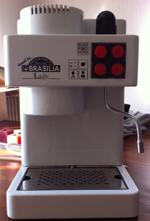 This is how the machine started out. This isn’t actually mine but I didn’t take a photo before I started. Mine was in much worse condition.
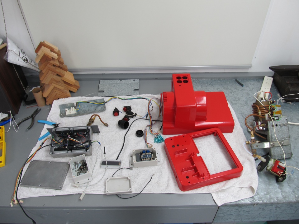
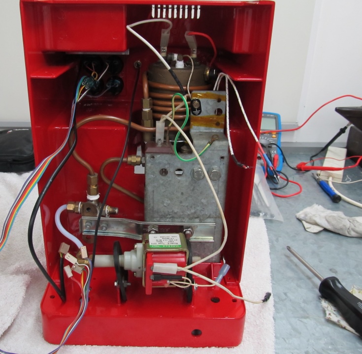
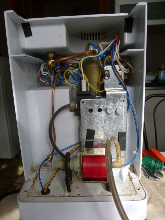 Very simplistic internals.
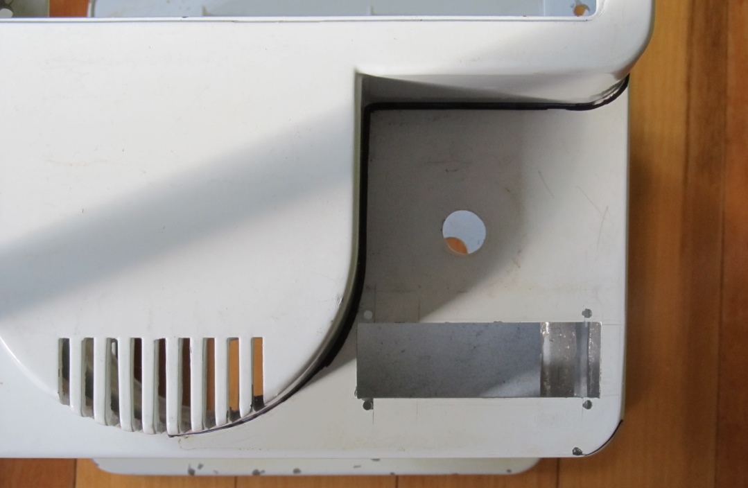
Top Panel
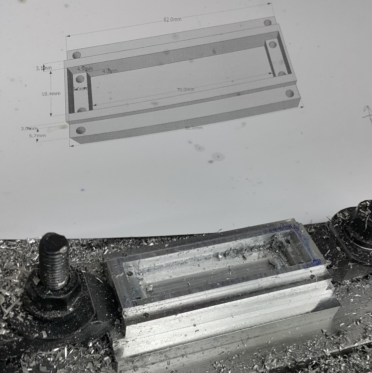
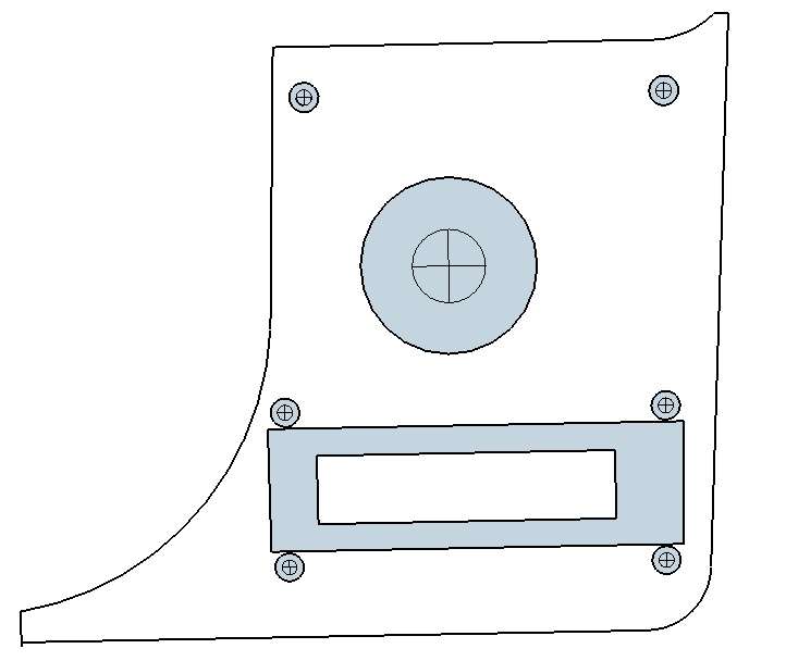 Template for top panel created in SketchUp
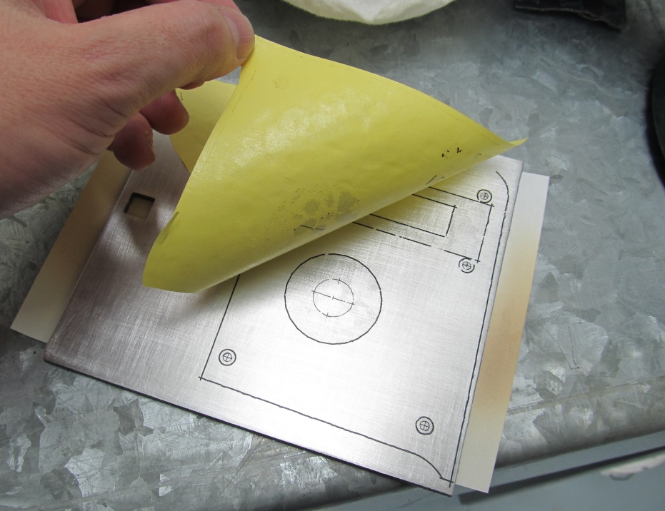
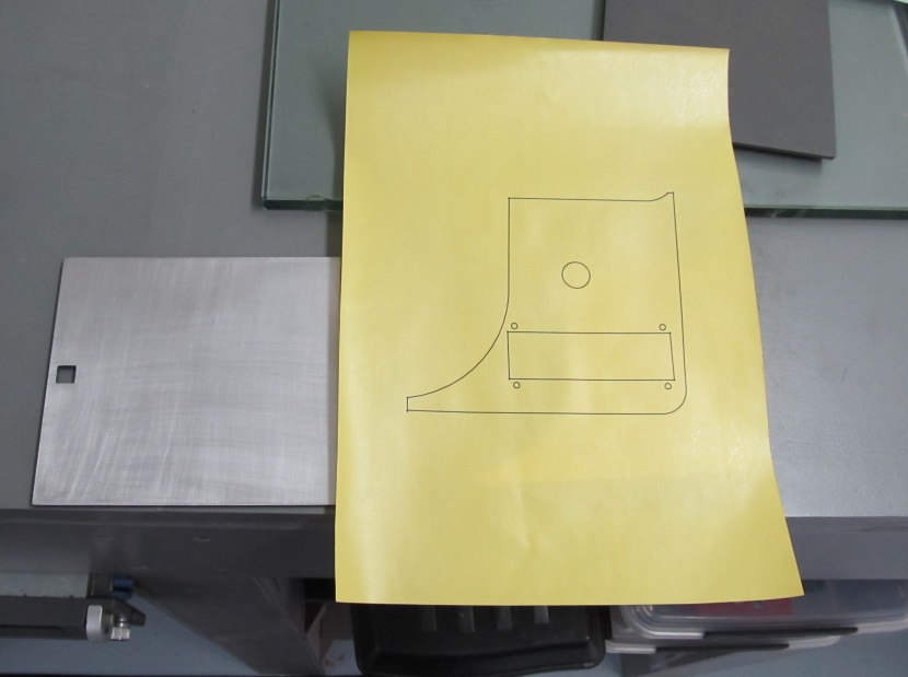 Template printed onto toner transfer paper
Thanks to Katt for the great idea of using [PCB transfer paper.
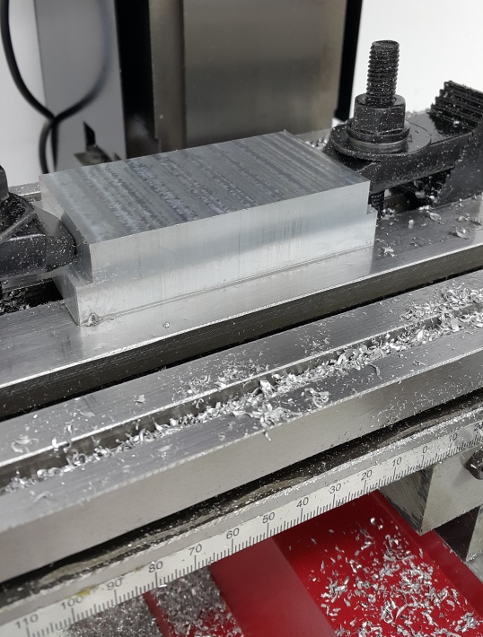
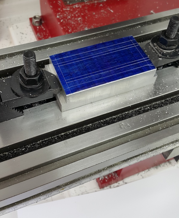
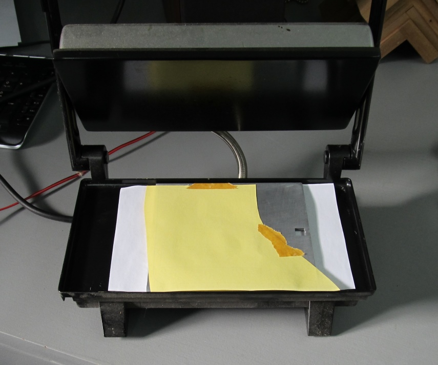 Template pressed onto 3.5MM aluminium plate with an old sandwich press
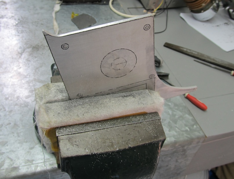
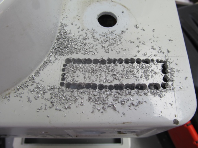
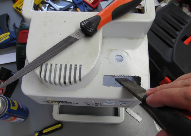
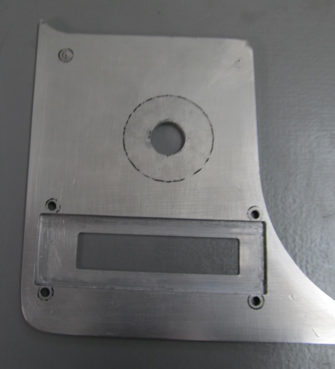
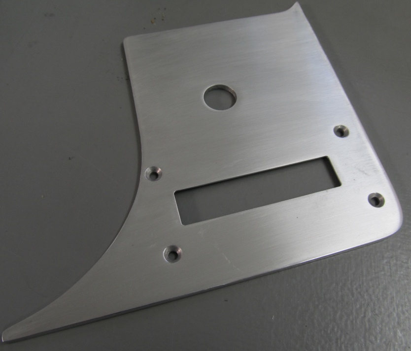
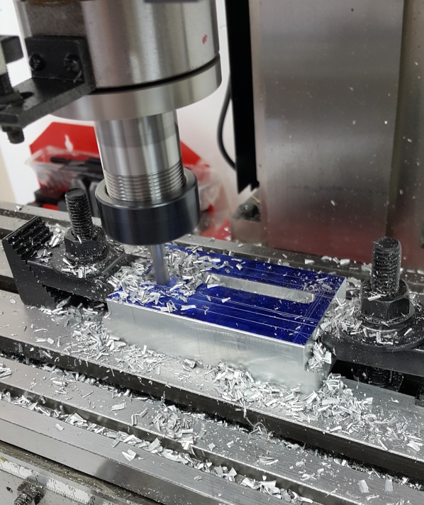
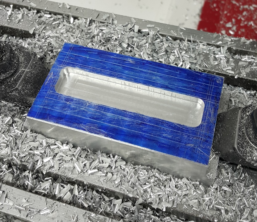
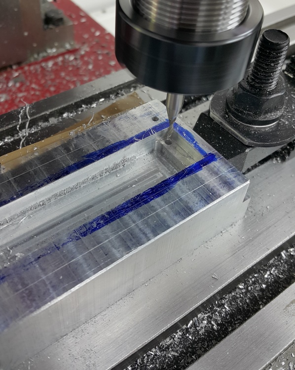
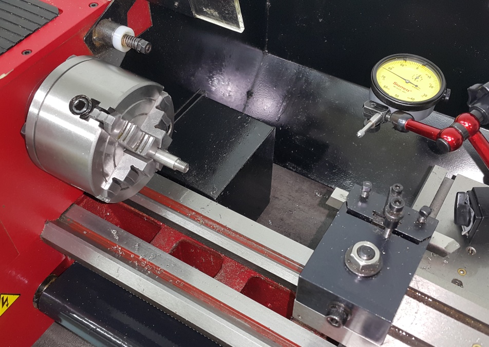
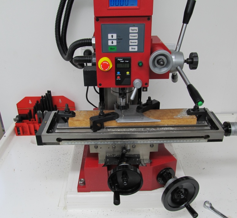 Milling the display aperture and a recess so that the display is very close to the surface of the panel.
This Sieg SX3 mill is proving to be very useful. It’s the same as the Grizzly G0619

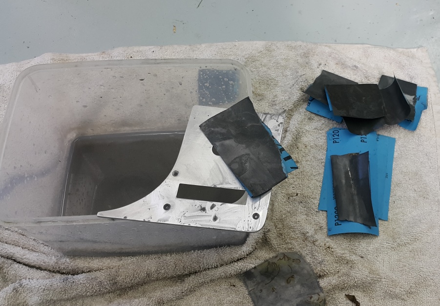
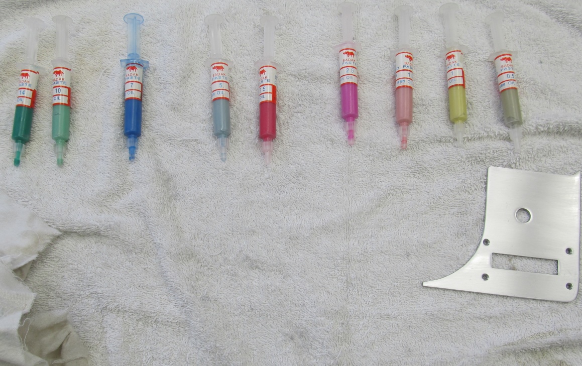 Polishing compounds in various grades
The polishing compounds came in a set of 12 syringes

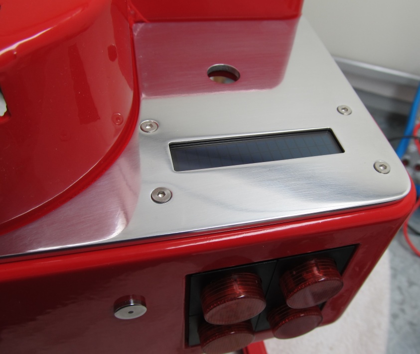
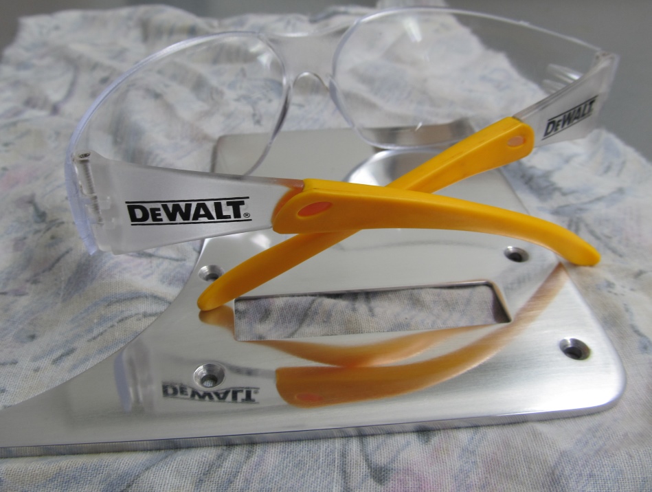 Shiny!
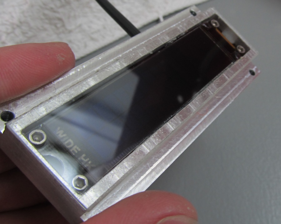
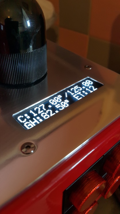
oLED Display Module
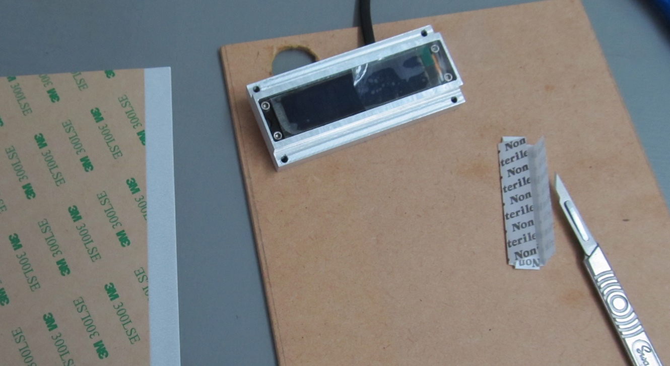
This 3M Double-sided tape
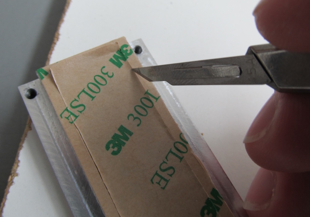
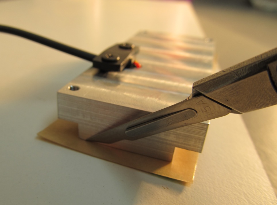
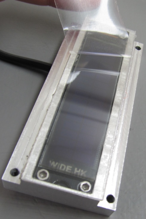
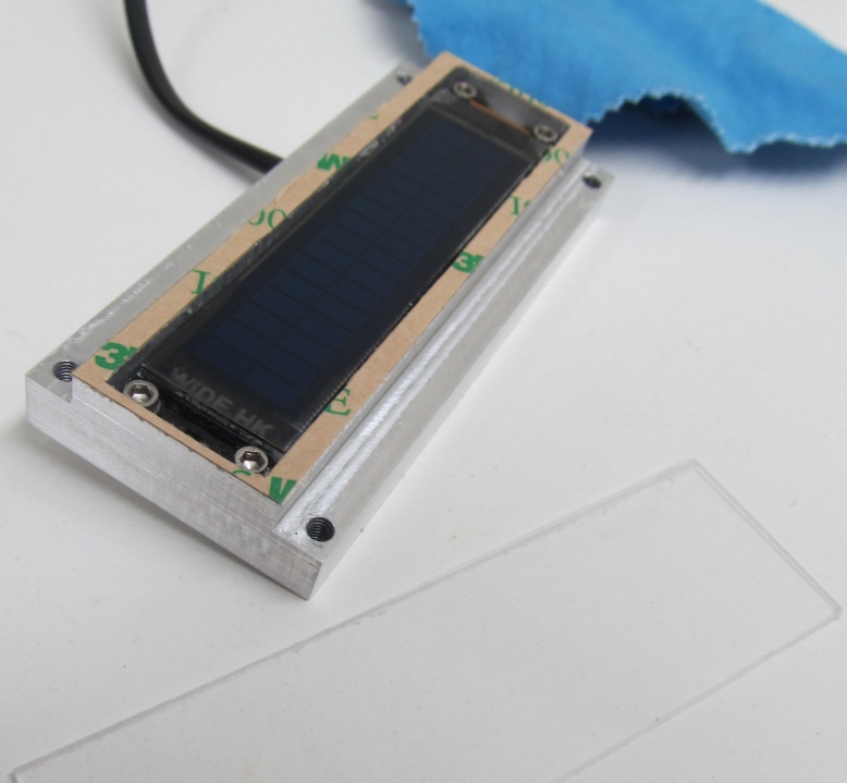 The clear acrylic lens is sealed to the display module with 3M double sided tape.
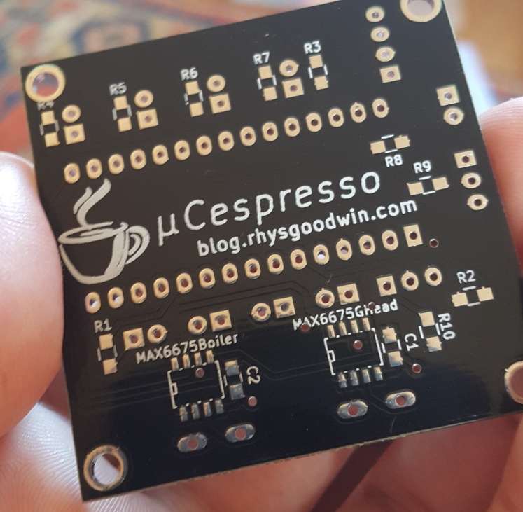
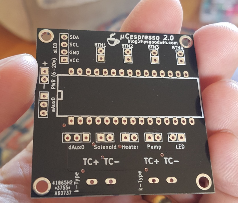
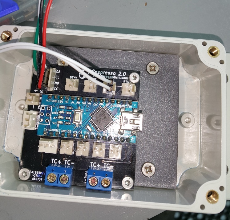
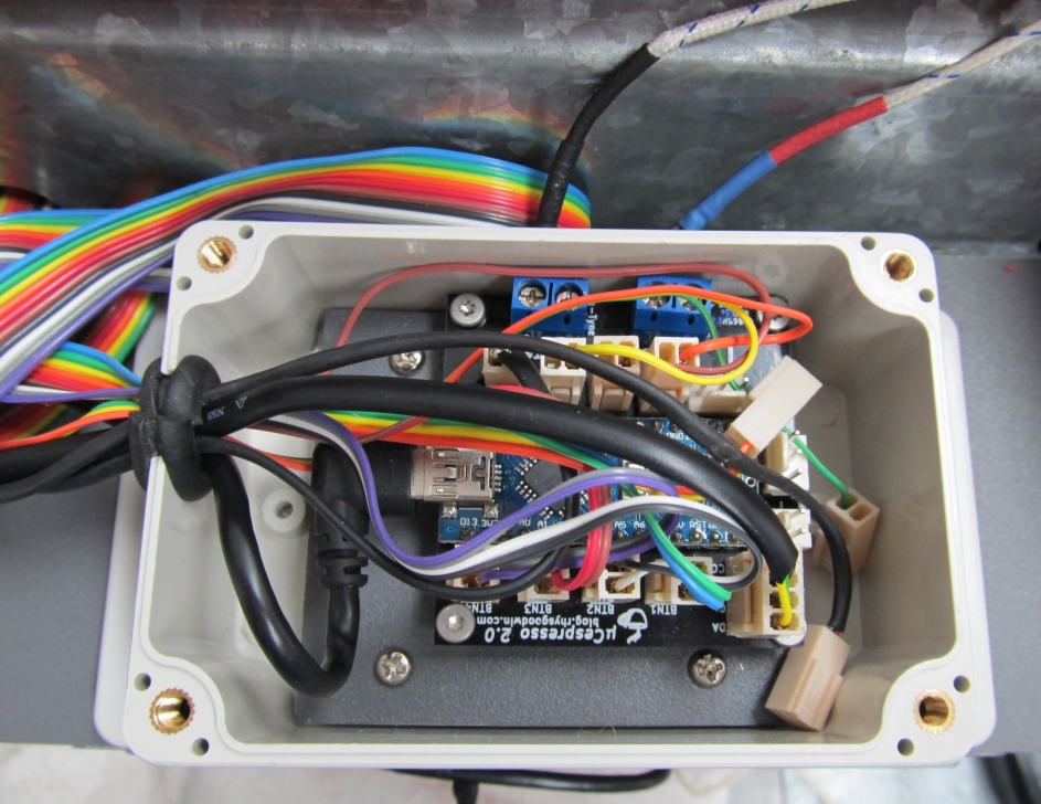
PCB and Controller
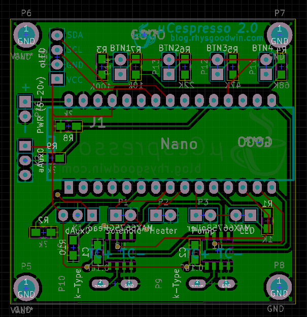 PCB design created in KICAD. Such an awesome piece of software!
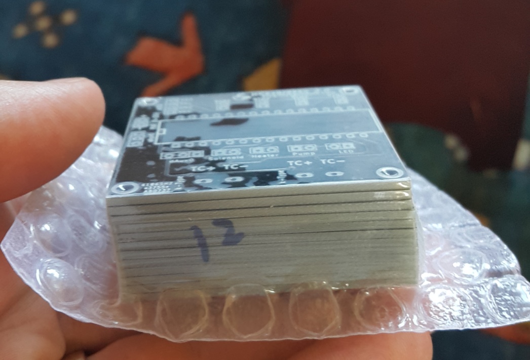
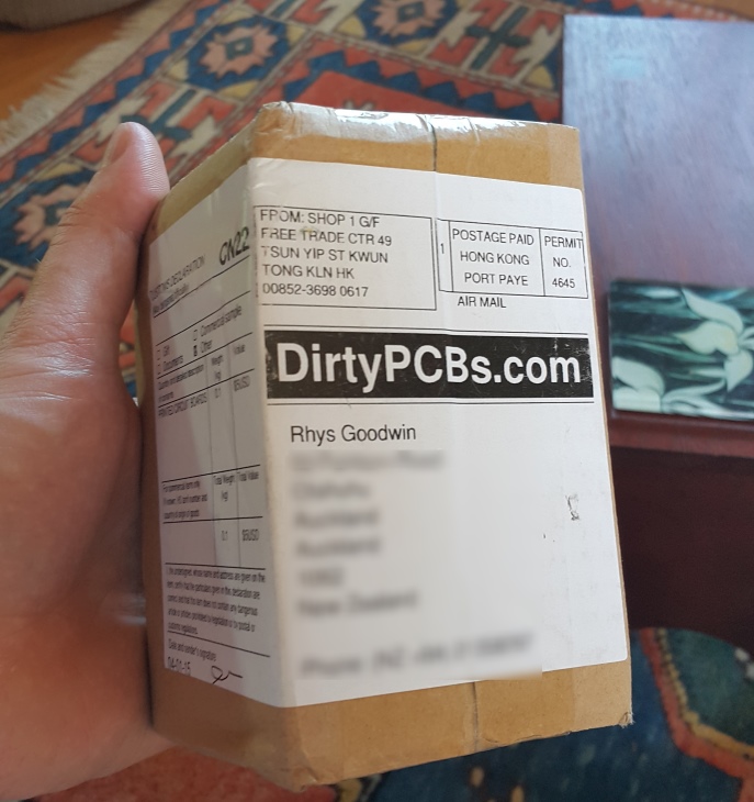 12 double layered PCBs delivered for $14 USD from DirtyPCBs.com. I’m not complaining!
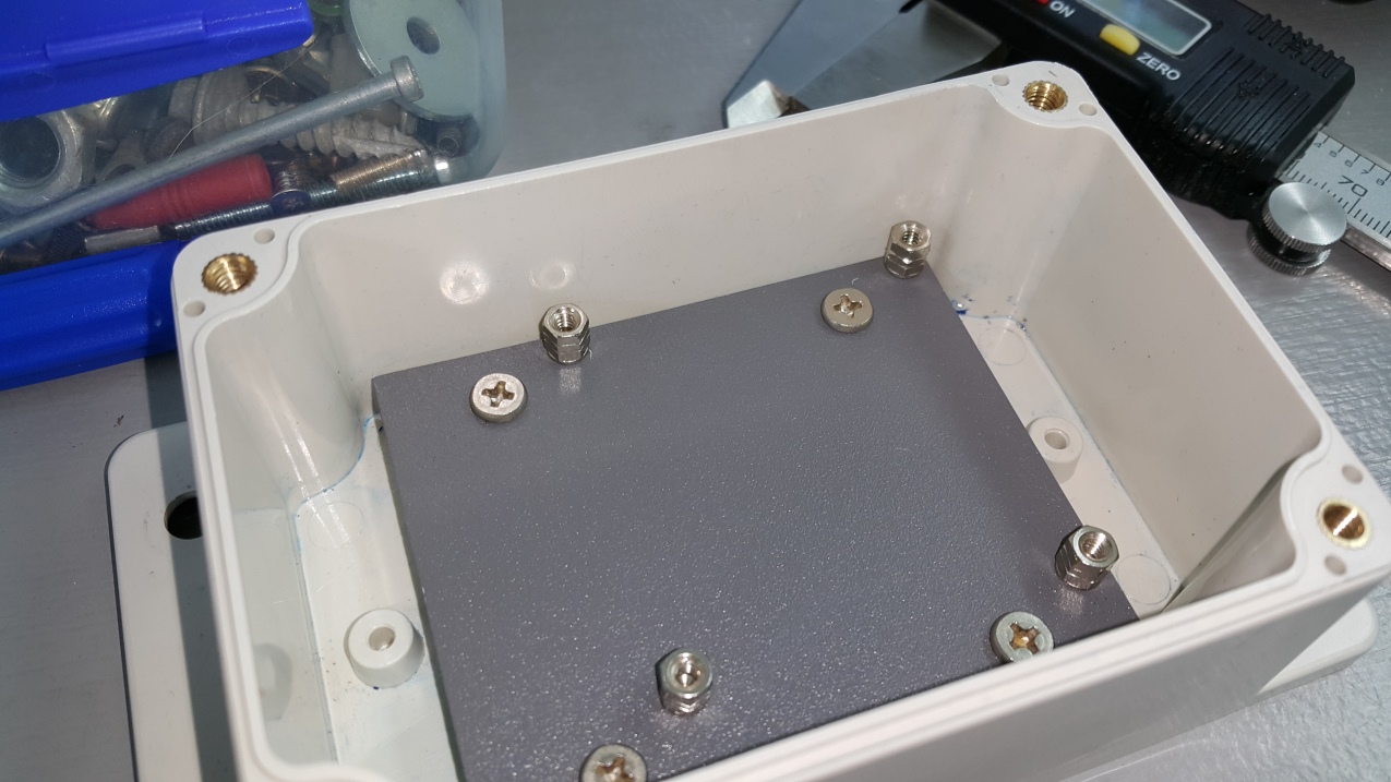
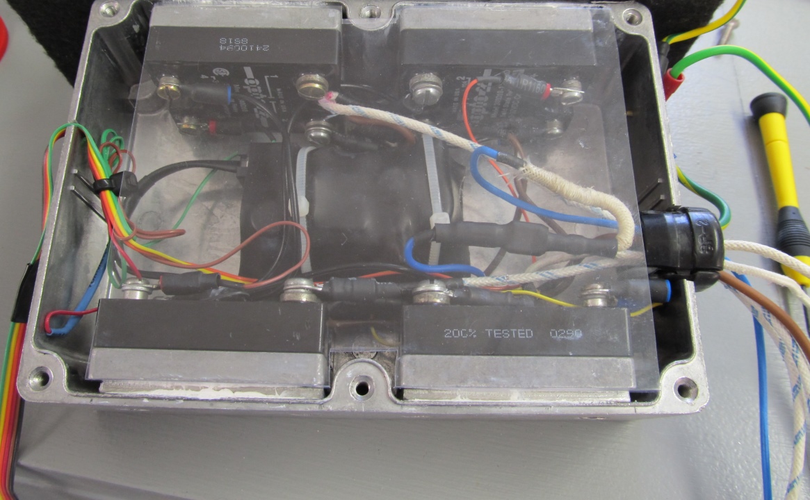
Power Box
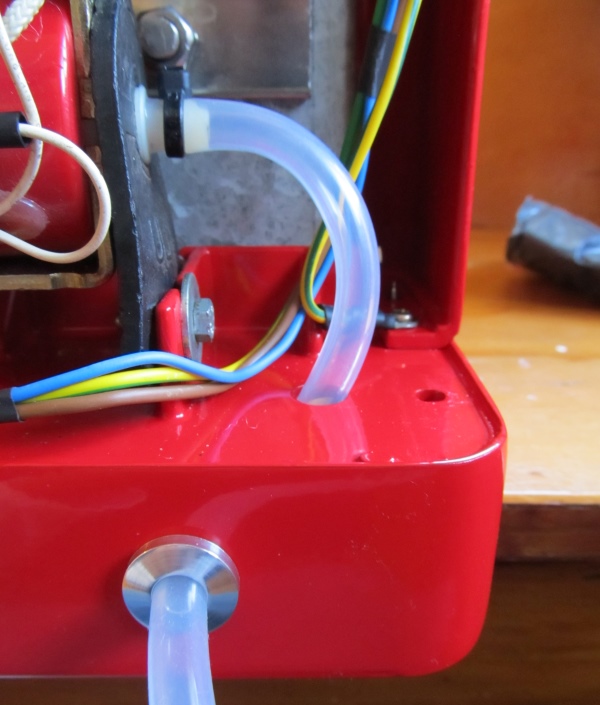
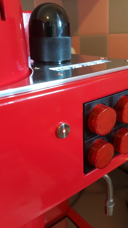
Front LED
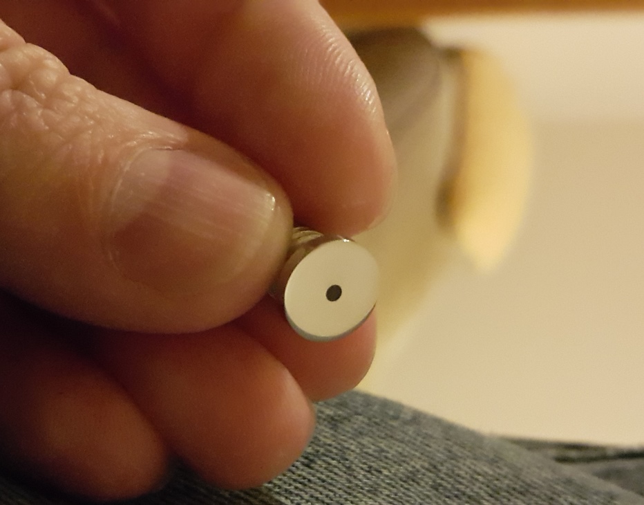 The led holder is made from stainless steel. A piece of fiber optic plastic is glued in as a lens.
Water Tank
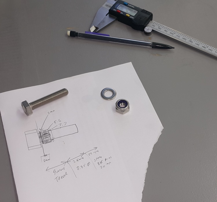
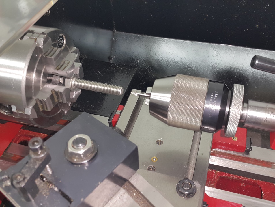
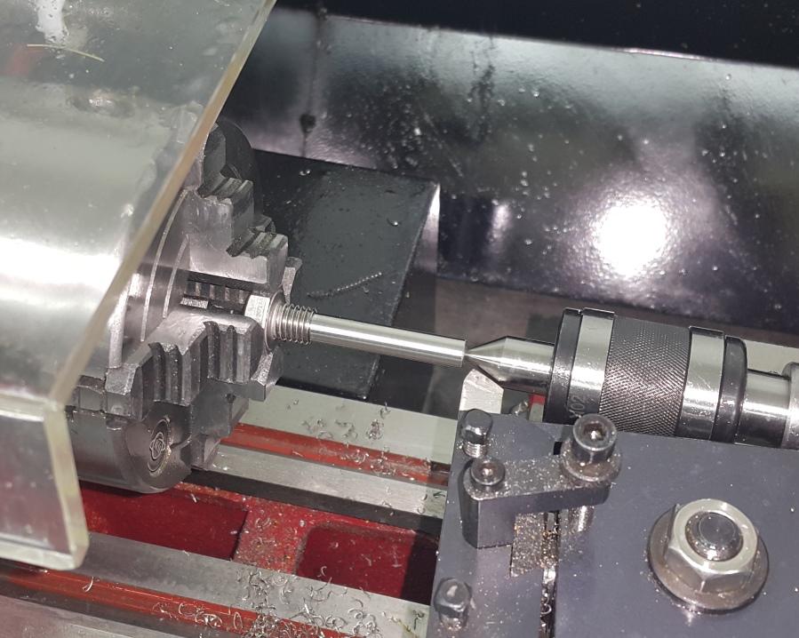
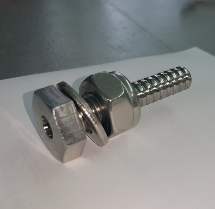
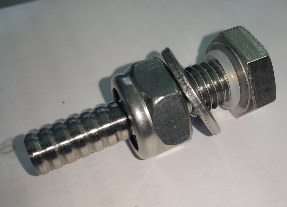
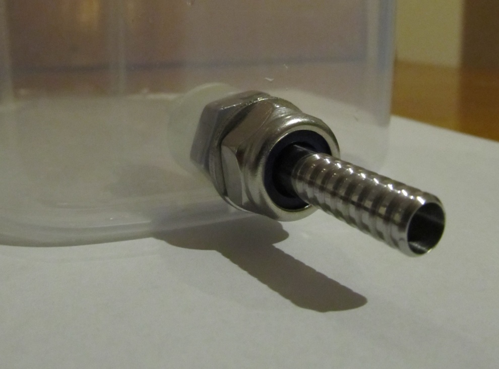
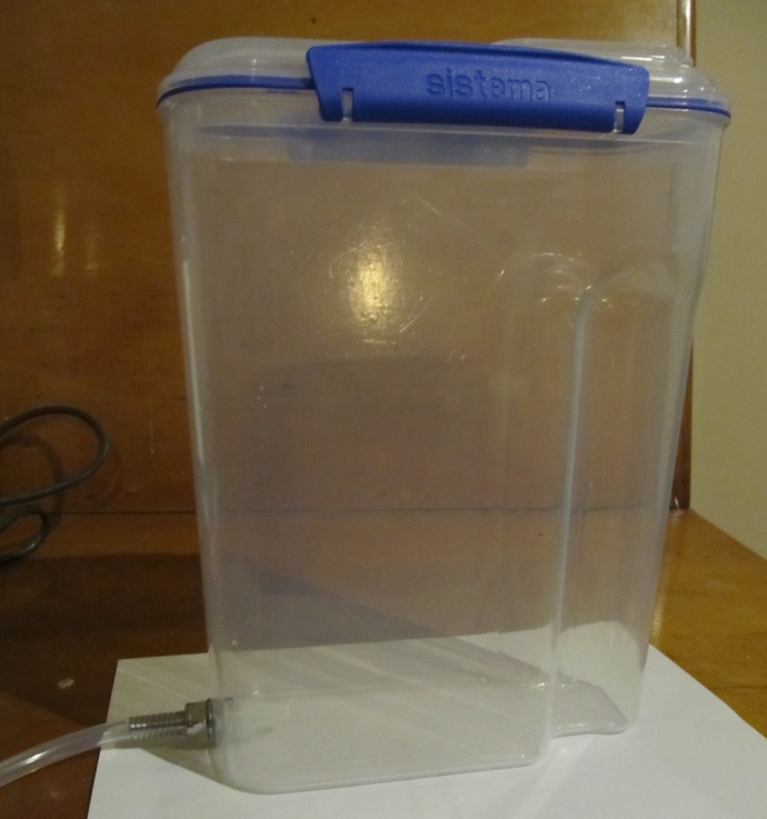
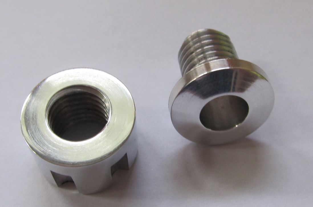
Water Inlet
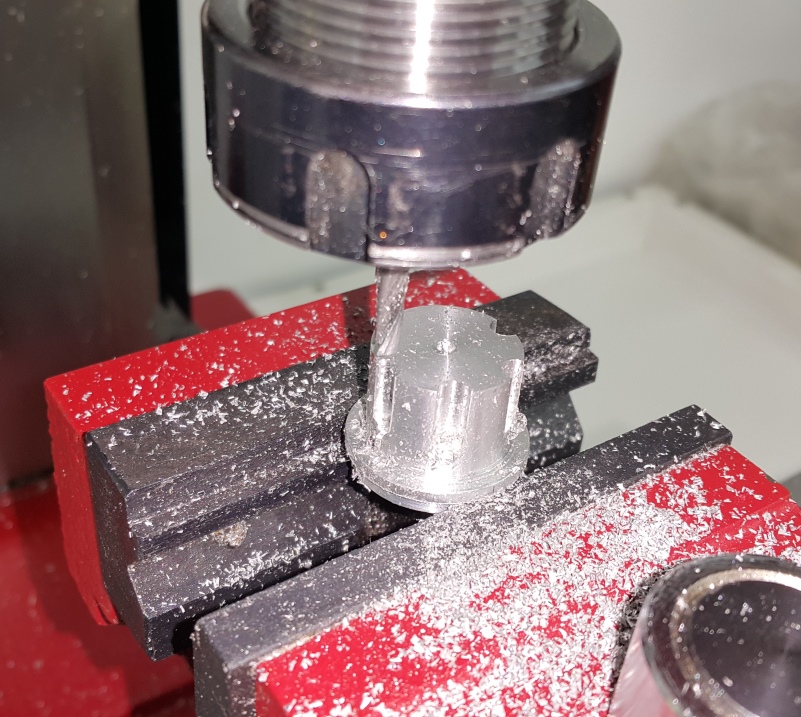
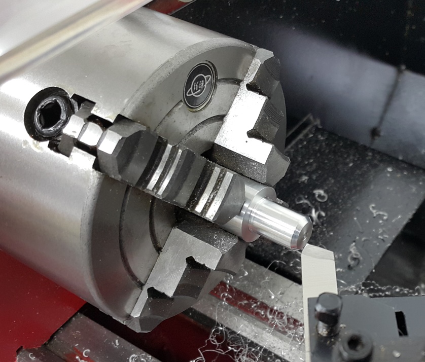
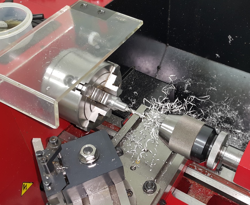
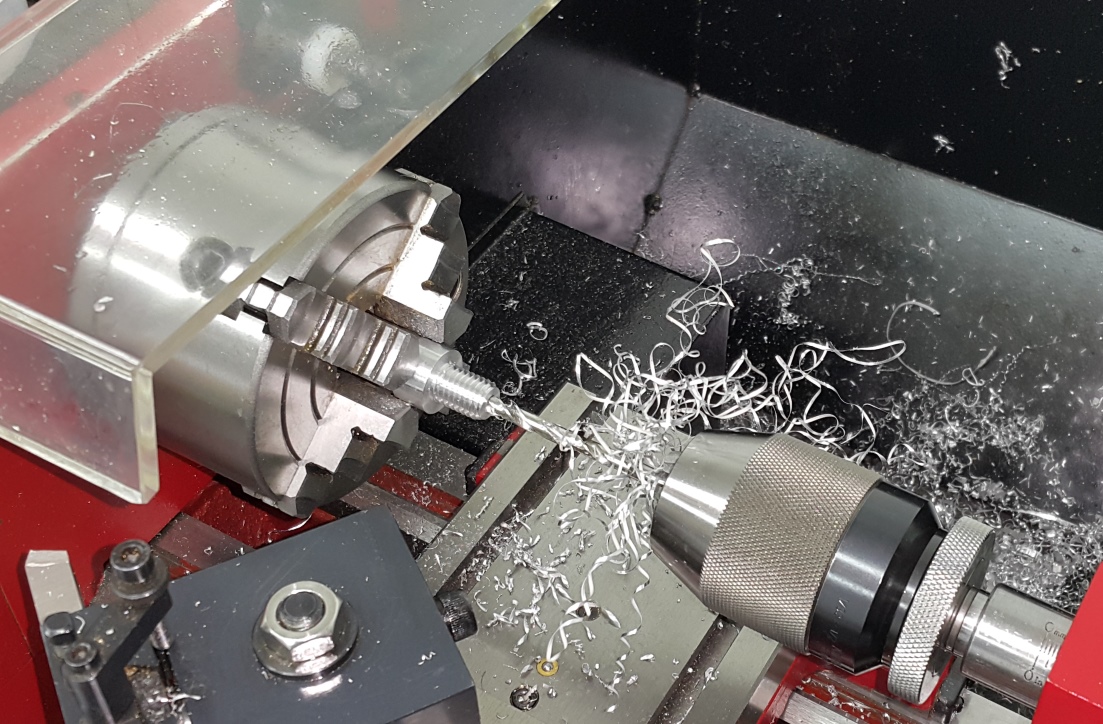
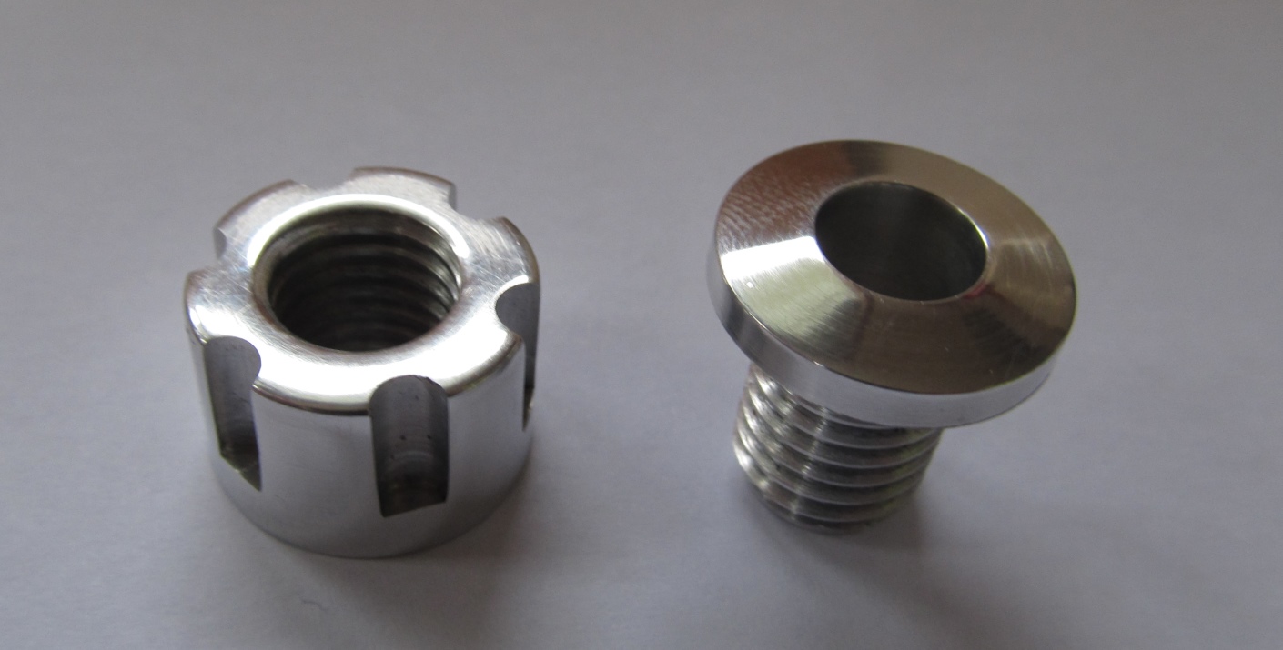
I’m not sure why I made such an elaborate nut for this considering it’s hidden inside the machine. Never mind it was fun.
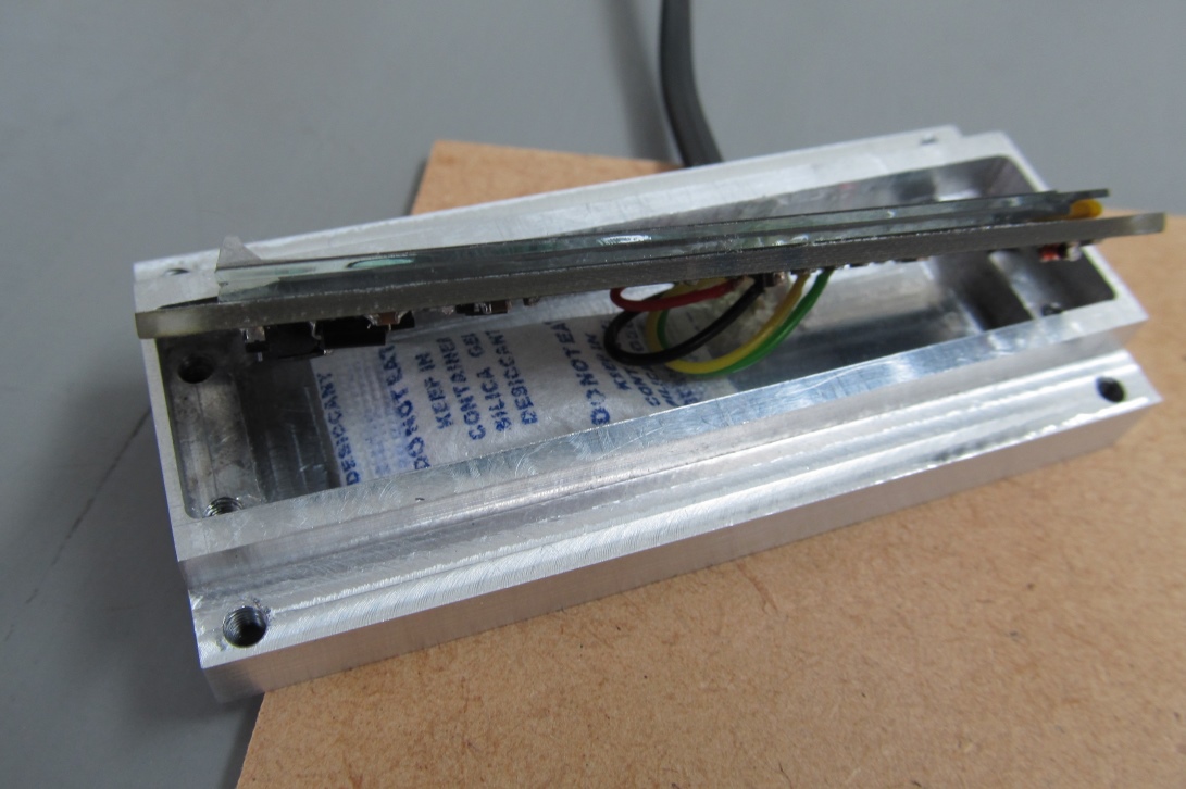
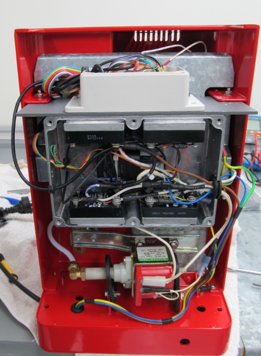
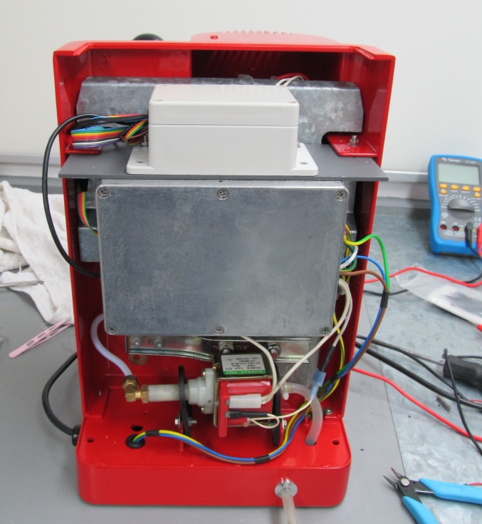
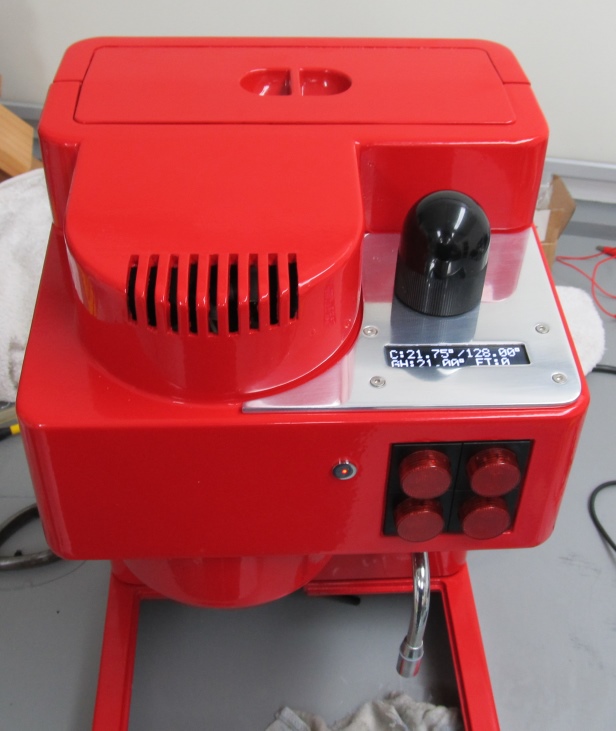
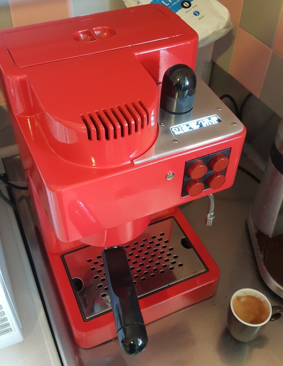
Final Assembly
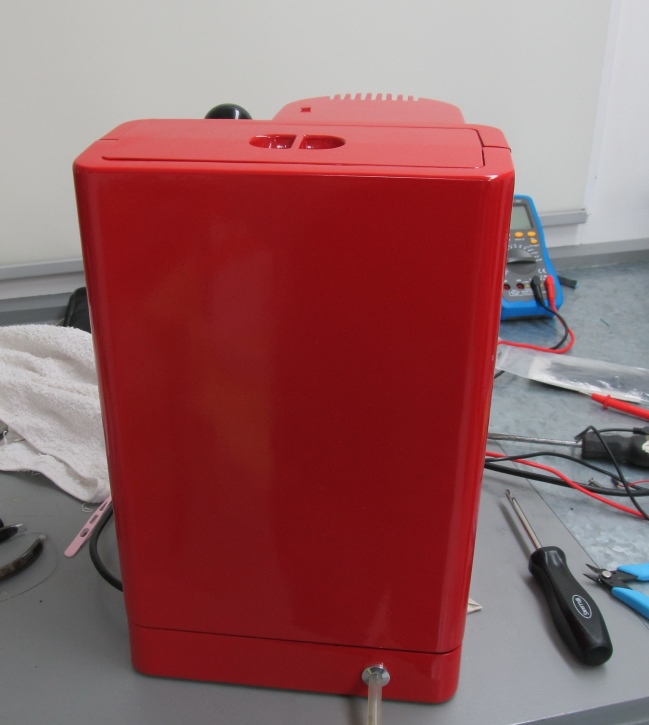
Before the final assembly I had the machine casing stripped and powder coated in flame red.
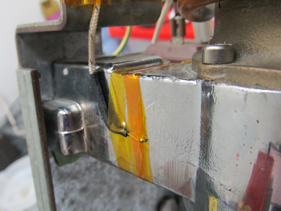 Group head temperature probe
The group head temperature probe is held on with High temperature Kapton tape

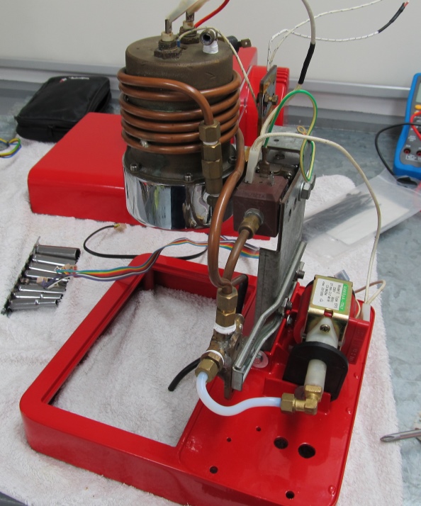 The tube wrapped around the boiler is a pre-heat tube that I added so that the water being drawn into the boiler is not stone cold.
Parts List: (Thanks China!)
- Top plate: 3.5mm Aluminium (from HP Server blanking panels)
- Display module: Cut from a block for 101 x 50mm Aluminium (New, local)
- Display: Hide.HK I2C 1602 LED display. (via eBay ~20USD)
- Display glass: Plexiglass 1.5mm (via ebay)
- Display Tape: 3M 300LSE 9495LE Double Sided Adhesive (sheets via AliExpress)
- PCB printed by DirtyPCBs.com
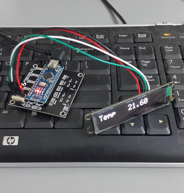
- Arduino Clone: Nano 3.0 clone (via AliExpress)
- 2x Temperature sensor chip: MAX6675ISA SPI Interface (via AliExpress)
- Connectors (via local JayCar Electronics)
- PCB Box (via AliExpress)
- Power Box – Aluminium (via local JayCar Electronics)
- Solid-State relays (Can’t remember had bunch in a parts box for years)
- DC power supply: From a Samsung USB charger
- Rubber grommet kit (via AliExpress)
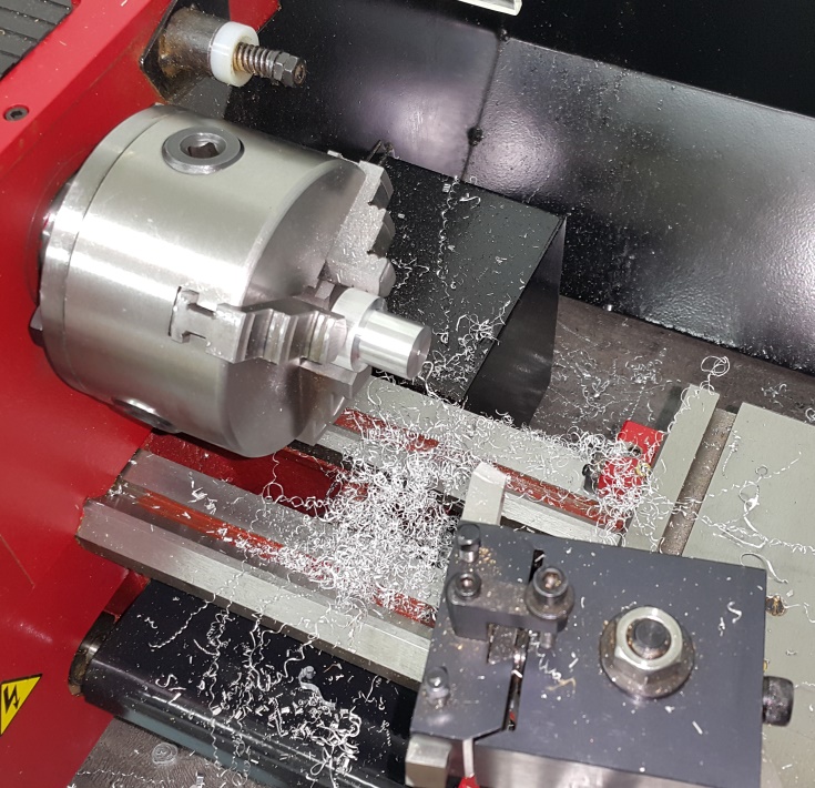
- LED holder: From some stainless rod I had lying around
- Water Take outlet: Stainless M10 Bolt
- Silicon seal for water inlet – from a kit (via AliExpress)
- Water inlet: 22mm Aluminum rod (New, local)
- Silicon tube: 6x9mm food grade (via AliExpress)
- Pre-Heat tube: 6.4mm (I think) copper (New, Local)
Thanks for stopping by. Feel free to ask questions.
Here is the source code and PCB schematic designs if anyone is interested. I’d be happy to have critique on either.
Update 2022-10-22
- If I were to do the PCB design again (i.e. I suggest you do this), use a separate IO pin for each button, don’t try to economise with 4 buttons off a single pin like I did. I’ve sometimes had issues with buttons being mis-read. It should be possible to make it more robust in the code but using separate inputs is going to make things less complicated.
-
Below is the code from the original post (0.75) and the latest code (0.78) which I’m currently running. You’ll notice in the current code that I’ve commented out a lot of code related to forced heating. I was previously disabling the PID while water was being pumped and setting the heater to a pre-set power level. This is because when we’re pumping in cold water, we don’t need to wait for the PID to realise and start adjusting. However, all this starting and stopping of the PID introduced a bug somewhere and sometimes the PID would just go haywire and overheat the boiler. Since commenting out all this code and just letting the PID do it’s thing, it’s been rock-solid. I’m sure the code could be improved a lot – I’m just a wannabe developer! At some point I should get this into a repo. Or if you make improvements feel free to do so and I’ll post a link to your repo here.
- uCespresso PCB
- uCespresso Arduino Code 0.75
- uCespresso Arduino Code 0.78