Transparent Firewall and Packet Mangler for SD-WAN Testing
Kia ora folks,
This is a quick recipe to build a transparent firewall and packet mangler. This can be used for things like SD-WAN testing where you place it transparently in-line between the WAN port and the uplink and use it to limit bandwidth, add latency, introduce packet loss/corruption, and block destinations. You can also use this arrangement for packet capture.
You can use a server, desktop, or VM with three network interfaces running Ubuntu Server 22.04. One NIC is for management and has an IP address so I can SSH to it. The other two NICs are configured in a bridge. Or 4 NICs for two bridges. I did my testing with a Hyper-V VM. For a VM make sure MAC spoofing is allowed for the two bridge NICs.
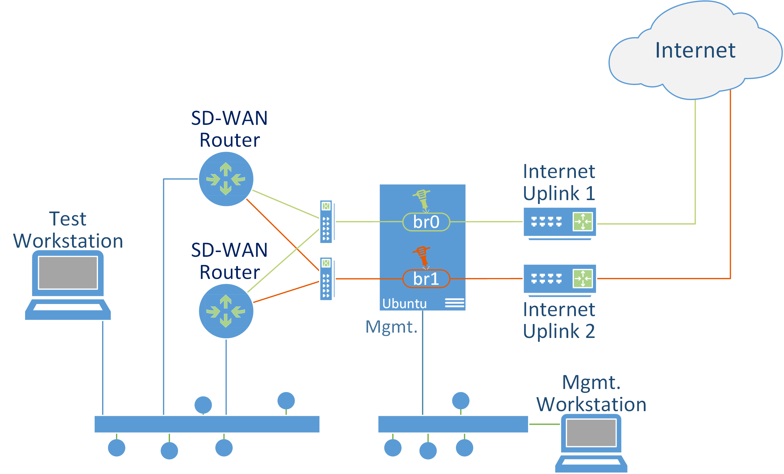
You can think of the two NICS in a bridge as an ethernet cable which connects the SD-WAN router to the internet uplink – an ethernet cable which can transparently manipulate the packets flowing through it.
I’m not going to go in to too much detail, just the main steps to get you going. Let me know if you have any questions and I’ll update the post as needed. The main tools we’re using are:
- tc: the Linux kernel traffic control utility. This is used for rate limiting and introducing packet loss etc.
- nft: the tool for managing nftables, the modern Linux kernel packet classification framework which replaces iptables. Both tools are vast so I’ll just provide some basic examples which will give you a starting point, after which you should be able to implement your own requirements using the reference documentation for these tools.
Steps
- Do a vanilla install of Ubuntu 22.04 server. The only extra component I enabled during the install is OpenSSH Server. The first network interface is given an IP address. The other two interfaces are left as DHCP for now.
- After the install, SSH to the box and configure the interfaces and the bridge using netplan by editing /etc/netplan/00-installer-config.yaml. You might have a static IP for your management interface. I’m using DHCP. The main point is that we’ve got two NICs with no IP configured in a bridge. Mine netplan looks like this:
network:
  version: 2
  ethernets:
    eth0:
      dhcp4: true
    eth1:
      dhcp4: false
      link-local: [ ]
    eth2:
      dhcp4: false
      link-local: [ ]
    eth3:
      dhcp4: false
      link-local: [ ]
    eth4:
      dhcp4: false
      link-local: [ ]
  bridges:
    br0:
      dhcp4: false
      link-local: [ ]
      interfaces:
        - eth1
        - eth2
    br1:
      dhcp4: false
      link-local: [ ]
      interfaces:
        - eth3
        - eth4
- Apply the config
netplan apply
Now that the basic networking is in place, confirm that things are working just as if you had a cable between the router and the uplink, then we can start messing with some packets.
tc
The first thing to consider is that these tc commands only apply to egress (outgoing) packets so if you want to manipulate both directions you need to apply your configuration to both interfaces. Just remember that for round trip latency it will be double. I.e. 30ms will be 60, likewise 10% packet loss on both interfaces will be 20%. I wrote some very basic shell scripts for different scenarios. In these examples I’m just working with br0 (eth1, eth2).
Scenario 1 - Rate limit and latency
#!/bin/bash
LATENCY="30ms"
RATE="50mbit"
tc qdisc del dev eth1 root
tc qdisc del dev eth2 root
tc qdisc add dev eth1 root netem delay $LATENCY rate $RATE
tc qdisc add dev eth2 root netem delay $LATENCY rate $RATE
The first two lines remove any existing qdisc config then we apply latency and a rate limit.
Scenario 2 - Packet Loss
#!/bin/bash
PACKETLOSS="10%"
tc qdisc del dev eth1 root
tc qdisc del dev eth2 root
tc qdisc add dev eth1 root netem loss $PACKETLOSS
tc qdisc add dev eth2 root netem loss $PACKETLOSS
There’s a lot you can do with tc and plenty doco and articles out there.
Here’s some links for tc:
- https://wiki.archlinux.org/title/advanced_traffic_control
- https://netbeez.net/blog/how-to-use-the-linux-traffic-control/
nft
Here we’ll implement a basic firewall with an accept policy, that is, everything will be allowed unless we block it. This is a bit different to the typical firewall which is normally also a router and controls traffic between two segments. With this config we’re firewalling traffic within the same LAN segment across the bridge. Here are some commands to get you started:
-
Add a table called ‘filter’ of family ‘bridge’
nft add table bridge filter -
Add a chain called ‘forward’ to the table which has a chain type of ‘filter’ and receives packets from the forward hook with a policy of accept. Accept is actually the default so this can be left off, but if you want to set the policy to drop and then add allow rules, this is where you would do it.
nft add chain bridge filter forward '{type filter hook forward priority 0; policy accept;}' -
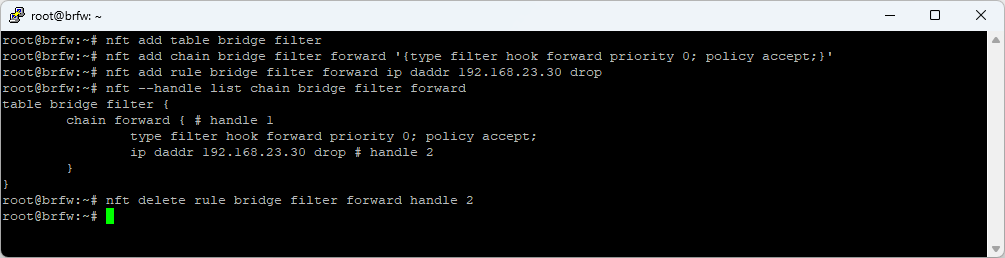
Add a rule to the chain to match packets for destination 192.168.23.30 and drop them. There’s a LOT of flexibility in how you can match packets
nft add rule bridge filter forward ip daddr 192.168.23.30 drop -
List rules in the table / chain and display the handle
nft --handle list chain bridge filter forward -
Delete a rule from the chain using its handle
nft delete rule bridge filter forward handle 2 -
Clear all tables, chains and rules
nft flush ruleset -
List the full rule set
nft list ruleset
Here’s some links for nft:
- https://wiki.nftables.org/wiki-nftables/index.php/Quick_reference-nftables_in_10_minutes
- https://wiki.nftables.org/wiki-nftables/index.php/Bridge_filtering
- https://wiki.archlinux.org/title/nftables
Update
Here’s a great series of posts I found some time after writing this article:
- https://www.excentis.com/blog/use-linux-traffic-control-as-impairment-node-in-a-test-environment-part-1/
- https://www.excentis.com/blog/use-linux-traffic-control-as-impairment-node-in-a-test-environment-part-2/
- https://www.excentis.com/blog/use-linux-traffic-control-as-impairment-node-in-a-test-environment-part-3/
That’s it! Happy packet mangling!
Ngā mihi nui
Rhys